RUNNING LED
It is basically a chaser circuit using a simple circuit using IC chips. It is very simple to construct Following are the components required for this
- CD4017 IC
- NE 555 Timer IC
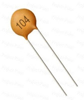
- 0.1µf Capacitor (3 nos)
- 1MΩ Variable resistor (preset)
- Three resistors of 1MΩ, 10KΩ and 100Ω
- 9V Battery or Power supply
- A Standard bread board
If you are a beginner choose a breadboard instead of PCB. The circuit diagram is shown below. Assemble all parts in the breadboard as per the circuit
Working
The working of the circuit is so simple. The key part of the circuit is the two IC chips. The 555 IC is a timer and the 4017 is a counter IC. Here the 555 IC which is used as an astable multivibrator. The output of the 555 timer is square wave. The time period of the square wave can be calculated using the following equation
T=0.69RC
The output of the timer is given to the 4017 counter which counts the sequence as per the circuit diagram by each of the clock pulses applied in the input.


No comments:
Post a Comment
keep supporting funwithelectronian.blogspot.com