FM TRANSMITTER

               FM Transmission is a common method in wireless communication which sends the low frequency  audio message in FM range (88 to 108 MHz). The transmitted message can be easily demodulated or decoded by the help of an FM radio receiver.
             The main components required are

  • 0.1uH Inductor
 Can be easily made by 6-7 turns of 26 SWG (0.45mm) winding wire
  • BC547 Transistor
  • 0-100pF Trimmer Capacitor 
  • Ceramic Disk Capacitors (22pF,0.001uF)
  • Resistors 
  • Audio input or Condenser Microphone 
  • Breadboard or PCB
CIRCUIT DIAGRAM 

                     Modulation is the process of superimposing a low energy low frequency signal into a high energy and high frequency carrier signal with changing of any of its properties like frequency, Amplitude or Phase. In the case of FM the frequency of the carrier is varied with the amplitude of message signal .
                    In the above circuit, the Inductor and trimmer capacitor constitutes a tank circuit which generates the carrier frequency. By adjusting the trimmer the frequency of oscillation can be varied.The transmitted signal from the FM transmitter is received and tuned by the FM receiver.
                

SIMPLE CELLPHONE CHARGING CIRCUIT

             A simple mobile phone charging circuit can be constructed from basic components. Here a zener diode and a transistor are the key components of this project. It is NOT suitable for daily purpose usage, but can be used to charge old cellphones. I'am explaining this circuit to only understand the basic working principle only. The main components required are,

  • BC 547 Transistor
  • 4.7 V Zener diode
  • 100uF Electrolytic Capacitor
  • 470 Ω resistor
  • Breadboard or PCB
CIRCUIT DIAGRAM
                The above figure is a series voltage regulator. The transistor is used as a control element and the zener used as a dtector. When the input supply voltage Vin increases the output voltage Vload also increases. This increase in Vload will cause a reduced voltage of the transistor base emitter voltage Vbe as the zener voltage Vzener is constant. This reduction in Vbe causes a decrease in the level of conduction which will further increase the collector-emitter resistance of the transistor and thus causing an increase in the transistor collector-emitter voltage and all of this causes the output voltage Vout to reduce. Thus, the output voltage remains constant.
             

ARDUINO DEVELOPMENT BOARD BASICS PART 2

            Lets continue talking about Arduino IDE. Arduino is a powerful solution for newbies. Let us discuss about a simple program. First open Arduino IDE and follow the path given below

File > Examples > Basics > DigitalReadSerial

It should open in a new program window as shown below 
            In the starting of the program  we can see a short description about the program followed by /* and */  indicates that it is a multi line comment which not considered during the execution of the program .  Also following that you can find a description followed by // which indicates they are single line comments. You can use these techniques to add important comments to your program.
            In the beginning of the program you can see that 
int pushButton =  2;
By closely observing the code you can find that the int is highlighted which means it is a function. int means that the function is an integer. Following that the word pushButton is a variable. The variable is just a word which holds the data provided by the = sign. You can set any name to a variable. Here = 2 indicates  it id digital pin 2 on the Arduino board. At the end of each statement it ends with ; which means that you are done with that function. You should provide ; to ending of each function.
Following that we have already discussed that the functions void setup() and void loop() are essential in writing the program code. void means that that function do not return any information back to the  program. The function setup() run only once in the program. But in the case of loop() which runs over and over in the program.
          The delay() function indicates the rate or speed of the process. It is expressed in milliseconds.  For example if we want to blink an led every second, after we turn it on we can place a delay(1000) which will make the processor sit there and do nothing for a second (1000 milliseconds). Delay is also useful in debugging and general flow control.

ARDUINO DEVELOPMENT BOARD BASICS PART 1

           An Arduino is a physical hardware which is very useful for electronic projects. The heart of an Arduino is a microcontroller chip which can be programmed by C programing language. It is very cheap and compact in size which can be very useful in robotics projects. There are various type of Arduino boards are available in the market such as Arduino uno, Mega, Nano...etc
             Talking about Arduino it consists of several connection pins as shown in the figure.  An Arduino can be used to analog to digital conversion and vice versa. As yo can see in the figure the left side pins A0 to A5 are analog pins and the right hand side consist of digital pins. The Arduino can itself provide  a constant DC voltage of 3.3V and 5V.
             An Arduino can be programed by the Arduino IDE which is a software installed on a desktop or laptop. The Arduino IDE can be downloaded from here.
                When you open the IDE it looks like this. When you first connected your Arduino board to your PC with the help of a USB cable you have to select your hardware in the IDE. For this select
Tools > port > Hardware name (Your hardware should appear  here).
Now your hardware is ready for programing.
                As you can see the program starts with two functions named void setup()and void loop(). In almost all Arduino programs these two functions are essential. The basic template of Arduino IDE is shown below

       void setup() {

//set up stuff to only run at the beginning 

}

    void loop() {

//which consist of the statements about the program

} 
We discuss all of these functions later.


CONDENSER MICROPHONE AMPLIFIER

           This circuit is basically a multi stage RC coupled amplifier. The main components required are following.

  • CONDENSER MICROPHONE 
  • 1K PRESET OR POT
  • BC147 AND BC149 TRANSISTORS 
  • RESISTORS 
  • CAPACITORS 
  • 6V POWER SUPPLY
  • BREADBOARD  OR PCB
CIRCUIT DIAGRAM 
                    The circuit is a multistage amplifier capable of amplify the low power signal generated by the microphone. Transistor BC149 utilise current series feedback the first stage. The second stage comprising transistor BC147 is connected in the voltage shunt feedback configuration. These two stages provide sufficient gain to pick up even the slightest whisper. 

VARIABLE POWER SUPPLY 1.5-24V

This simple circuit is bridge rectifier circuit can be used to power the circuits described in my previous blogs. The main  components required are listed

  • 240/24 V 1A Transformer
  • LM317 Voltage Regulator
  • IN4001/4007 Diodes

  • Potentiometers/variable resistors
  • Resistors
  • Capacitors
  • Breadboard or PCB
CIRCUIT DIAGRAM
              The transformer is used to step down the 240V AC supply to 24V. Bridge rectifier converts this AC to the Direct Current. This pulsating DC is filtered using the capacitor to get a clean DC and is given to the input of LM317 voltage regulator IC. Depending on the variations in the potentiometer the output gets varied. It is necessary to use a heat sink along with the IC because it became hot while the operation.

AUDIO AMPLIFIER USING TDA2003 IC

This is a simple audio-frequency (AF) amplifier using the amplifier IC TDA2003.  The main components are
  • TDA2003 IC
  • 10K Pot
  • 8 ohm loudspeaker 
  • Resistors 
  • Capacitors
  • Power Supply 6V
  • Breadboard or PCB
The circuit diagram shown below 
            The IC can easily deliver 10W to a 4 Ohms load at 18V DC supply voltage. The IC can be also operated from 12V and that makes it applicable in car audio systems. The useful features of TDA2003 include short circuit protection between all pins, thermal overload protection, low harmonic distortion, low cross over distortion etc.

7 SEGMENT DISPLAY COUNTER CIRCUT

It is a simple circuit to drive the 7 segment display. The circuit consist of a 555 timer IC and CD4033 counter IC. The main components required are

  • CD4033 counter IC
  • 555 timer IC
  • 7 Segment Display
  • Resistors
  • Capacitors
  • Bread board or PCB
  • A suitable power supply of 5V DC
     CIRCUIT DIAGRAM
                 The working of the circuit as same as mentioned in my Running LED project. The 555 Timer is used in astable mode of operation and the generated clock pulse is given to the clock input of the counter IC. You can also implement the circuit using CD4017 IC. The circuit and calculations are same as in my Running LED project. 

CRYSTAL TESTER

Crystal is used as an oscillator, to generate a high frequency. In all the major electronic projects crystal is used instead of coil. Using this circuit you can analyse that your crystal working or not.The main components are

  • BC550 Transistor 
  • IN4007 Diodes
  • LED
  • Reistors(Values are specified)
  • Capacitors(values are specified)
  • Breadboard or PCB
CIRCUIT DIAGRAM
                 This electronic circuit consists of a crystal oscillator, two capacitors and a transistor forming a Colpits oscillator. A combination of diodes and capacitors are used for rectification and filtering respectively. Another NPN transistor is used as a switch to make the LED glow.
                The entire circuit is operated with two transistors, two diodes, and few passive components. If the testing crystal is good then it operates as an oscillator in combination with transistor. The diode rectifies the output of the oscillator and the capacitor filters the output. This output is now fed to the base of the transistor and the transistor starts conducting.
                 An LED is connected to the collector of the transistor through the resistor. The LED gets proper biasing and starts emitting light, i.e. it starts glowing. In case if any fault occurring in the testing crystal then the LED does not glow.


WATER LEVEL INDICATOR ALARM


This simple transistor based water level indicator circuit is very useful to indicate the water levels in a tank. Whenever tank gets filled, we get alerts on particular levels. The main components required for this project are,

  • BC547 Transistor
  • LEDs
  • Resistors(Value is specified in the circuit )
  • Buzzer
  • Battery(9V)
  • Breadboard or PCB
CIRCUIT DIAGRAM
               Here we are using transistor as a Switch. Initially there is no voltage applied to the base of the Transistor Q1 and the transistor is in OFF state and no current is flowing through collector and emitter and LED is OFF.
               When the water level reaches to Point A in the tank, the positive side of the battery gets connected to the base of the Transistor Q1 through the water. So when a positive voltage has been applied to the base of the Transistor Q1, it gets into ON state and current starts flowing from collector to emitter. And RED LED glows. 
                Here the resistors R4,R5,R6 are used to drop down the base voltage to 0.7 V.

BATTERY MONITOR CIRCUIT FOR 12 V LEAD ACID BATTERY

            Here is a simple Battery Monitor circuit for a quick check of 12 volt Lead-Acid Battery. Battery charge should be constantly monitored to increase the life of the battery. Overcharge as well as under charge will reduce the battery life. The terminal voltage of the Lead Acid battery should be with in the range of 12.5 to 13.5 volts. If the battery voltage reduces below 10 volts for long period, battery will not accept any charging current. Similarly if the terminal voltage exceeds above 14 volts, battery will be destroyed.
 The components required are

  • BC547 Transistor
     
  • Zener Diodes(Values re specified in circuit diagram)
  • LEDs(Red,Green and Yellow)
  • Resistors(Values are specified in the circuit)
  • Capacitor(Value is specified in circuit)
  • 12V lead-acid battery
  • Breadboard or PCB
CIRCUIT DIAGRAM
          The circuit is a Zener controlled transistor switch lighting three LEDs Red, Green and Yellow to show battery states like Low, Normal and High. When the battery voltage is less than 11 volts, Zener diodes Z1 and Z2 cease to conduct and Red LED only lights indicating low battery condition. If the voltage is between 12 volt and 14 volts, Zener diode Z1 forward bias and T1 conducts. The Green LED connected to the collector of T1 lights indicating normal voltage. If the battery voltage exceeds 15 volts, Zener diode Z2 also conducts and T2 forward bias. This lights Yellow LED indicating over charge. Thus the following indications can be obtained
                                      Red                                 Low voltage
                                      Green                            Normal voltage
                                      Green and Yellow         Over voltage

PANIC ALARM CIRCUIT

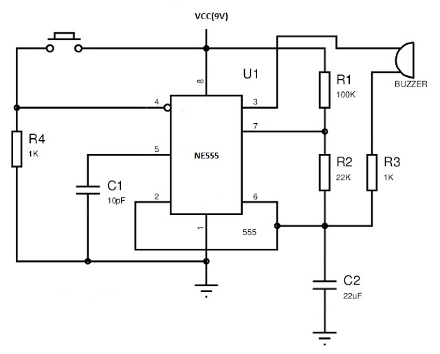
       Hello guys. This is a simple alarm circuit by using 555 timer IC in mono stable mode of operation. The components required are

  • NE555 IC     
  • A piezo-electric Buzer
  • Resistors (Values are specified in the diagram)
  • Capacitors(Values are specified in the diagram)
  • Push button switch
  • Power supply or 9V battery
  • Breadboard or PCB
The circuit diagram is shown below
WORKING
                The working of the circuit is based on the mono-stable operation of the 555 timer. The circuit is in the disabled mode when the switch is not pressed. When the switch is pressed it operate in the mono-stable state only. The IC is enabled only when pin 4 of the 555 given a high voltage which happens only when the switch is pressed.

3D LED CUBE 8x8x8

            An LED cube is basically a 3 Dimensional display which can display graphical images and animations in 3D. In this article I am ...