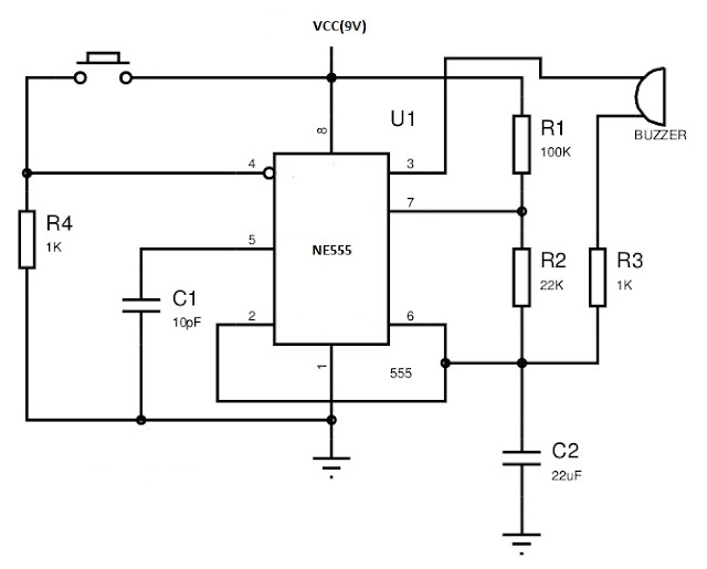
Hello guys. This is a simple alarm circuit by using 555 timer IC in mono stable mode of operation. The components required are
- NE555 IC
- A piezo-electric Buzer
- Resistors (Values are specified in the diagram)
- Capacitors(Values are specified in the diagram)
- Push button switch
- Power supply or 9V battery
- Breadboard or PCB
The circuit diagram is shown below
WORKING
The working of the circuit is based on the mono-stable operation of the 555 timer. The circuit is in the disabled mode when the switch is not pressed. When the switch is pressed it operate in the mono-stable state only. The IC is enabled only when pin 4 of the 555 given a high voltage which happens only when the switch is pressed.


No comments:
Post a Comment
keep supporting funwithelectronian.blogspot.com