WATER LEVEL INDICATOR ALARM


This simple transistor based water level indicator circuit is very useful to indicate the water levels in a tank. Whenever tank gets filled, we get alerts on particular levels. The main components required for this project are,

  • BC547 Transistor
  • LEDs
  • Resistors(Value is specified in the circuit )
  • Buzzer
  • Battery(9V)
  • Breadboard or PCB
CIRCUIT DIAGRAM
               Here we are using transistor as a Switch. Initially there is no voltage applied to the base of the Transistor Q1 and the transistor is in OFF state and no current is flowing through collector and emitter and LED is OFF.
               When the water level reaches to Point A in the tank, the positive side of the battery gets connected to the base of the Transistor Q1 through the water. So when a positive voltage has been applied to the base of the Transistor Q1, it gets into ON state and current starts flowing from collector to emitter. And RED LED glows. 
                Here the resistors R4,R5,R6 are used to drop down the base voltage to 0.7 V.

BATTERY MONITOR CIRCUIT FOR 12 V LEAD ACID BATTERY

            Here is a simple Battery Monitor circuit for a quick check of 12 volt Lead-Acid Battery. Battery charge should be constantly monitored to increase the life of the battery. Overcharge as well as under charge will reduce the battery life. The terminal voltage of the Lead Acid battery should be with in the range of 12.5 to 13.5 volts. If the battery voltage reduces below 10 volts for long period, battery will not accept any charging current. Similarly if the terminal voltage exceeds above 14 volts, battery will be destroyed.
 The components required are

  • BC547 Transistor
     
  • Zener Diodes(Values re specified in circuit diagram)
  • LEDs(Red,Green and Yellow)
  • Resistors(Values are specified in the circuit)
  • Capacitor(Value is specified in circuit)
  • 12V lead-acid battery
  • Breadboard or PCB
CIRCUIT DIAGRAM
          The circuit is a Zener controlled transistor switch lighting three LEDs Red, Green and Yellow to show battery states like Low, Normal and High. When the battery voltage is less than 11 volts, Zener diodes Z1 and Z2 cease to conduct and Red LED only lights indicating low battery condition. If the voltage is between 12 volt and 14 volts, Zener diode Z1 forward bias and T1 conducts. The Green LED connected to the collector of T1 lights indicating normal voltage. If the battery voltage exceeds 15 volts, Zener diode Z2 also conducts and T2 forward bias. This lights Yellow LED indicating over charge. Thus the following indications can be obtained
                                      Red                                 Low voltage
                                      Green                            Normal voltage
                                      Green and Yellow         Over voltage

PANIC ALARM CIRCUIT

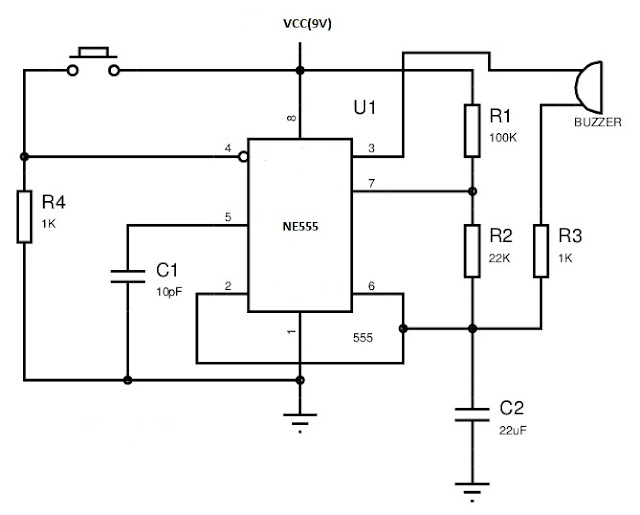
       Hello guys. This is a simple alarm circuit by using 555 timer IC in mono stable mode of operation. The components required are

  • NE555 IC     
  • A piezo-electric Buzer
  • Resistors (Values are specified in the diagram)
  • Capacitors(Values are specified in the diagram)
  • Push button switch
  • Power supply or 9V battery
  • Breadboard or PCB
The circuit diagram is shown below
WORKING
                The working of the circuit is based on the mono-stable operation of the 555 timer. The circuit is in the disabled mode when the switch is not pressed. When the switch is pressed it operate in the mono-stable state only. The IC is enabled only when pin 4 of the 555 given a high voltage which happens only when the switch is pressed.

SOUND REACTIVE LED

We can easily make a sound reactive LED by following the simple circuit. The main components which you need for this project are listed below.

  • TIP31 NPN Power transitor

     
  • Couple of LEDs
  • Power supply (9V)
  • Breadboard or PCB
CIRCUIT DIAGRAM
           The working of this circuit is based on the input signal applied to the base of transistor. The collector current varies with the amplitude of the audio signal. 

POLICE LIGHT CIRCUIT

This is the mot simple way for implementing the police light circuit. The main components are listed below.

  • NE555 Timer IC (2 Nos)
     
  • LED (Red and Blue)


  • 12V Power Supply
  • Resistors(Values as shown in circuit diagram)
  • Capacitors(Values as shown in circuit diagram)
  • Breadboard or PCB
CIRCUIT DIAGRAM
WORKIG
           
           Both 555 ICs are cascaded which works as astble multivibrators, each of them with a different freqency. Their otputs are connected to two groups of LEDs. The frequency and nature of flashing can be adjusted by changing the values of R and C as mentioned in the previous circuits. You can change the number of LEDs, but it is necessary to adjust the value of R1 not exceeded the maximum current of LEDs.    

Dancing LED circuit

DANCING LED CIRCUIT

            It is  a simple circuit constructed by a couple of resistors, capacitors and a par of NPN transistors. The components and materials required are listed as follows
  • 2N3904 Transitor
             
  • Resistors
  • Capacitors
  • Bread Bord
  • A power source or Battery
     The circuit diagram is shown below
Working
               The circuit is basically a square wave generator which having two states either high or low. The frequency or time period of the square wave are decided by the value of resistor R and capacitor C. When the circuit is powered on either one of the transistor will become ON. At that time the other transistor is off position. For an example assume that the first transistor is on and he second is OFF. At that time the first capacitor C1 starts to charge and when it charges to approximately 0.7V The second transistor will be ON and starts to conduct Hence LED 2 will become glow. At that time Transistor Q1 become OFF and the second capacitor C2 charges by R. This process continues and the output is a square wave. 
              The time period can be calculated by the equation
      T=0.69RC

For example designing a time period of 1 second the values be
Assuming the value of capacitance be 100uF
1 = 0.69(100 × 10^-6)𝑅 
     R=15K

3D LED CUBE 8x8x8

            An LED cube is basically a 3 Dimensional display which can display graphical images and animations in 3D. In this article I am ...